segunda-feira, 20 de abril de 2009

GlowPad

HTML clipboard

MetkuMods

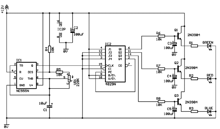
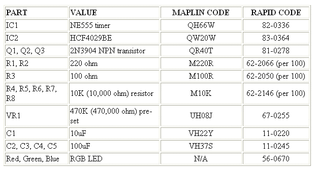
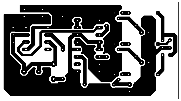
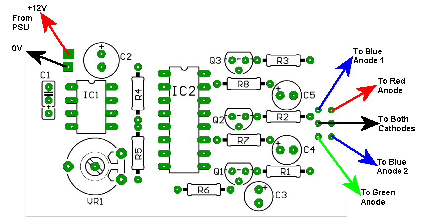
First time in English. Please, be easy on me :)

So, this is the project that I started to do something about these old and outdated mouse pads, maybe to add some more "glow" to them.

First the tools. Just a regular saw that you can get from any hardware store. This is used to cut out the basic shape of the pad.
Some files to smooth out the shape. I found the file with rounded profile worked best in this pad without straight lines and 90 degree corners.

Dremel multi to make modifications to the basic shape and to carve the channel for the wires and leds. There is also a picture of cutting wheels which were used.

I bought the plexi from a firm specialiced in plastics. They sell these surplus peaces priced by weight. I found this clear 500x500x5mm piece and payed 45 FIM for it (~$6).
We start out by measuring and marking the wanted size of the pad. I chose 250x200 mm, maybe a little oversized but there have to be some spare space around the pad to work with.

Powered up my Dremel and rounded the corners to make the shape more pleasing.

Then I started to file the edges. At this moment you can decide how big area is lit by the light. If you file more towards the center of the pad, those areas will be lit. For the smaller area, just round the edges slightly.

I decided to have all the wiring inside the pad so I wouldn't have to place any risers to the sides of the pad to lift it from the table surface.

Took my Dremel again with a different drill bit and started to carve. You have to try to make that channel deep enough. The leds I chose are 5 mm, same as the plexi and we have to get them placed inside and parallel to the plexi. You have to file some material off the leds too. 1.5-2 mm from the diameter should do it.
I bought 2 superbright leds from the local component dealer. These are 12-16 candela leds with 2.1 V and 20 mA forward current. Angle of the light beam is 8 degrees.
Cost me 15 FIM piece ($2). Quite expensive but these are SUPERbright, 16 candelas is a lot.

Operating voltage is taken from the PSU of the computer with a standard molex connector. Use RED for + and BLACK for the - (ground). This gives us +5 volts to work with.

I have connected the leds in parallel and added one 82 ohm resistor. That resistor is used to sink that extra 3 volts that is not used (5 V - 2.1 V =~3 V). The resistor also adds a possibility to adjust the brightnes of the leds. Just choose a resistor with the higher resistance and the leds get dimmer.

You can also add a regular on-off switch if you want to power down the lights.

First tests.

I used some tape to place everything as they should be. Connected the pad to adjustable powersource and WOW, it worked. The light is even brighter and better that I hoped, cool :)

Just to point out. That green color on the pad is from protective film that is applied for the protection of the plexi. You should try to keep it on till the end of the project. Keeps those nasty scratches and greasy finger prints off.
I just had to try superbright blue leds. These are 4.2 candela versions. A lot brighter than normal blue leds.

I left those red leds in just for the extra fun. That really looks nice. Maybe I'm a little cheap but I didn't leave those blue leds in. The cost like 35 FIM ($5) piece here in Finland.
I removed the protective film. As you can see from the picture, only the edges are lit. Just as I wanted at the moment.
You could carve that channel more closer to the edge of the pad. I didn't want to because I use an optical mouse so I need to place some material, ie. a cloth over the pad. This cloth makes the optical mouse operation possible and it will also hide the leds. If you use a mechanical (a regular) mouse you might not want to add anything.
Bonus.

I just had to find out how can I make my own pictures or text to be visible on the pad. This is actually really easy. Just take your Dremel or very sharp spike and draw the image.

You only have to make very shallow lines. I think that in that letter M, I carved like under a millimeter away and it works great.

This gives me an idea. Why not use this same technique for example in case windows. Just trace your favourite image and place the plexi like a regular case window. Power up and behold your latest creation, "flying image" because it will be floating in midair and only the lines will be lit.

Maybe no words are needed for this :)
Added 07.12.2001

I tested this technique to smaller plexi piece. As a result I got this quite nice happy face that one can place on the top of the computer or on the night stand.

I used 3 mm green led that costed like $0,07. One 1.5 volt battery wasn't enough so I used two. 68 ohm resistor is needed to limit the voltage so the led doesn't get too hot.

Great Christmas present if you use better integration or maybe to be used as an case badge?! ;)

Added 07.12.2001

And some more carving.

Made this little sign to be placed over the server machine. Could be placed over the monitor etc. One thing I noticed is that it's best to carve the image on the back side of the plexi as an mirror image. After that just flip the plexi over and add the lights. It's a lot brighter this way.

So there you have it. A GlowPad. It took me like two days to make. Now I think that it would only take few hours. This is a really easy way to boost up your fame in LAN parties or in your office. Now it's your turn to make one. Good luck :)

PS. Thanks to my brother for being a bench vice during this project.

02.2006

So this was the tutorial that introduced the lighted mousepads to the world. This was also the article that demonstrated plexi carving for the first time. These days there are many manufacturers that use this same technique to make lighted mousepads that we invented back in 2001. It was quite funny to notice that people would be willing to spend many times more money for one, rather than make their own glowing playground for the mouse. :)

-Jani

Rainbow LED

bit-tech.net

Author: Dave Williams
Published: 28th August 2002

Somewhere, over the rainbow...
Right, let's get straight to the point. This is a little eye-candy circuit which continuously cycles an RGB LED through the colours of the rainbow. The speed at which the colours change is adjustable.

The circuit has two options:

1. Switch between the different colours. This makes the effect very noticeable.
2. Have the colours fade into each other. This is a more relaxed effect and one I find very pleasing. The choice is yours.

The cost is about £2 (ish) plus the LED and PCB

At this point I was planning on having a video of the circuit in action but the exposure on my video camera is only fully automatic. This makes it impossible to get even a half decent clip of a concentrated light source such as an LED. Anyway, the concept is pretty straight forward so your imagination should give you the picture.

Moving swiftly on, here's how the circuit works:

IC1, C1, R4, R5 and VR1 form a standard "555 timer" based pulse generator. The frequency of which, and hence the speed of the effect, is adjusted using the pre-set VR1.

These pulses are fed into IC2, a 4029 binary counter whose outputs continuously count in a binary progression between 1 to 7. These outputs drive the transistors Q1, Q2 and Q3 which, in turn, control each of the three colours of the RGB led.

The pulses are"shaped" by passing them through an RC network before they reach their respective transistors. This "shaping" produces the fading effect between the colours.

The fade in/out time can be altered by changing the value of the capacitors. (C3, C4, C5). Reducing the value to 47uF will reduce the time to fade between colours. Conversely, increasing the capacitance to 200uF will take longer. The value of 100uf for the "fade" capacitor was found by testing to be the most suitable over a wide speed setting range. You may want to experiment with different values, especially at very high and low speed settings. Do not change the R6, R7 and R8 values as this will affect the led current and may damage it.

As stated previously, the circuit can be used without the fading effect and having the colours abruptly change. To do this, just do not fit the fade capacitors, C3, C4 and C5.


A note about the led limiting resistors, R1, R2 and R3. The values shown in the table were derived from calculation and then trimmed to the nearest preferred value by experimentation. The chosen values produce good results without over loading the led. If you use an RGB led with different specs, you may need to use different resistor values, although the circuit should still work using the current values.


The PCB foil pattern below is clickable for a 4x life-size image. Use the 4x image to produce the art work to make the board. The image needs to be reduced to 25% when printing to produce the life-sized foil. Load the foil pattern image into a drawing package such as Paint Shop Pro to print it. Do the reduction at the PRINTING stage and NOT using the resize image tools within the drawing package. Using this reduction method produces sharp artwork.

EAGLE users can download the PCB layout here. The free version of EAGLE can be downloaded here. Or from the Eagle web site download page.

The board size, (the rectangle around the foil), is 34mm x 61mm.

All holes are 0.8mm with the exception of the holes for VR1. These are 1.2mm.

When assembling the PCB start with the smallest components first, working your way up. (Resistors, IC's, transistors, pre-set, capacitors).


RGB LED Specs

RED If = 30mA, Vf = 2.0V
GREEN If = 25mA, Vf = 2.2V
BLUE If = 30mA, VF = 4.5V

LED pin outs viewed from underneath.


Here's a picture of the completed Rainbow LED. The led can be mounted off board using wires which will make it easier to panel mount.

Nifty-Stuff.com

Nifty-Stuff.com

Nifty LED Chicken Printers?

http://www.nifty-stuff.com/

floppy drive blue LED mod

plugnpray.co.uk logo
This mod has been done by lots of people before, so what better than the classic blue LED floppy drive mod as the first article in the modding section.

Before we get started I must direct your attention to our disclaimer and point out that opening your floppy drive will almost certainly void its warranty and if that didn't resoldering some of it components definitely will. There is not that much that can go wrong with this mod but plugnpray.co.uk accepts no responsibility for any damage caused whilst carrying out this mod.

That’s that out of the way, now to get on with the modding. The aim of the mod it to revamp a tired looking floppy drive by replacing the boring green LED with a nice high brightness blue one.

Equipment

  • Fine screwdrivers (philips and flat head)
  • Soldering iron
  • Solder
  • Needle nose pliers
  • Side cutters
Components That was nice and simple, not many tools required and the entire mod should only take about 15mins at most. The next step is to find an unsuspecting victim. I have chosen this Mitsumi drive that has been in my machine for the past couple of years, this was only £5 from a fair so if I go wrong all is not lost.
The Mitsumi floppy drive before the mod.

Now we have the drive we have to open it up, the first step with most drives is to depress the tabs that hold the front bezel on and it should pop off and end up looking something like this.
The drive with the front panel removed.

As shown in the picture above, once the bevel is removed the LED that needs replacing is now exposed. I would not recomend trying to resolder in this state, so locate the screws that hold the bottom panel on and remove them. With a bit of sliding the drive should separate leaving you with something like this:
The bottom panel removed.

At this point depending on your drive you may be able to access the LED to desolder it but in this case the LED is directly mounted to the circuit board which the motor assembly sits on, so it has to come out as well. Again just a few more screws and it comes away quite easily.
The motor assembly removed for easy soldering.

In the photo above I have folded back the ribbon cable that connected the motor to the rest of the drive to make soldering it easily. That’s the disassembly finished now it is time to put the new LED in.


That’s the drive apart now to change the LED which is really quite easy. All you have to do is place the soldering iron on the solder where it holds the legs to the board wait a second or so for the solder to melt and pull the old LED away.
The original green LED that is going to be removed.

Now for the trickiest bit of the mod, working out which way round to put the LED in! If you don't have a multimeter the long leg on the LED is the positive one, which is really helpful I hear you say if the circuit board is unmarked like mine was. If you look carefully at the LED you will see a flat part of the LED this denotes the negative terminal, then make sure you checked which way around your original LED was before you removed it and line your new LED the same way round.

The contact patches where the old LED was removed. The replacement Blue LED
Here you can see where I have desoldered the LED and on the right you can see the new LED with it legs bent to match the shape of the old one so it will fit in when we put it back together, mine was mounted to the surface of the board, hence the shape of the legs, different manufacturers mount them in different ways so just bend it so it will fit. Now just solder the new LED in, simple, snip of the excess from the legs and that’s it. All you have to do is reverse the disassembly process and you should end up with a perfectly functioning drive that looks a bit different.

The finished article in situe.

Here it is in all its glory, a very simple cheap and quick mod to make your machine stand out. Related Links

domingo, 19 de abril de 2009

LED Mod

Fórum do Clube do Hardware

[Fotos e Diagrama]
Eu tinha uns LEDs aqui da época que eu colocava nas motos e resolvi colocar no gabinete, ao invés de comprar um Cathode.

E para minha surpresa, no próprio gabinete Blue-Eye da Leadership, já tem espaços próprios para colocar as chaves liga-desliga.

Inclusive com opção de travar ela para funcionar no modo: cima/baixo ou direita/esquerda.

Vejam:


Então instalei 6 LEDs Brancos Alto Brilho. Usei um molex que eu tinha aqui. E coloquei 3 LEDs na parte de cima e três LEDs na parte de baixo.

Fotos do Antes e Depois:


Diagrama:


Um abraço,

Peter